|
Flow diagrams for oil management systemsBased on specification, operating conditions, compressor version, etc. there are different possibilities to design a parallel system. In the following we are showing general system diagrams which could be modified or combined.
Flow diagram OCS 1 with low pressure oil reservoir
Several oil separators (7) are used to separate the oil from the compressor discharge gas and return this oil to the oil reservoir (2). When more than one separator is used, it is essential to fit a RV-10B/0,1 (3) check valve at the oil separator outlet in the return line from each oil separator. This will ensure that oil cannot flow from one separator to the other as the float valves do not open and close together. ESK oil separators are described in our catalogue in detail on pages 18 ff.
In the oil reservoir (2) the oil is decompressed by the pressure valve RV2-10B/1,5 (1) and returned to the compressor via an oil level regulator (5). In front of the regulator a strainer (4) should be installed.

1 Pressure valve RV2-10B/1.5
2 Oil reservoir OSA
3 Check valve RV-10B/0.1
4 Strainer F-10B / F-10L / FF-10B
5 Oil level regulator OR .. / ERM6..
6 Suction line accumulator FA..
7 Oil separator OS / BOS2
8 Compressor
9 Check valve RV
Flow diagram OCS 2 with low pressure oil reservoir
One central oil separator (7) separates the oil from the compressor discharge gas. This is the system installed most frequent in practice. The oil separator is to select according to the total performance of the system. The working process is same as described for OCS 1.
Application of suction line accumulators and multi-accumulators for parallel systems
Compressors in parallel operation have to be protected by a suction line accumulator depending on application conditions. For the parallel operation of up to 4 compressors standard multi-accumulators are available.
The accumulators are described in detail in our catalogue on pages 50 to 56.
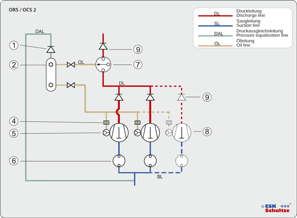
1 Pressure valve RV2-10B/1.5
2 Oil reservoir OSA
4 Strainer F-10B / F-10L / FF-10B
5 Oil level regulator OR .. / ERM6..
6 Suction line accumulator FA..
7 Oil separator OS / BOS2
8 Compressor
9 Check valve RV
Flow diagram OCS 3 with low pressure oil reservoir
Compressor, two stage, one oil separator per compressor
The crankcase of two stage compressors keeps normally the INTERSTAGE pressure. To get the oil from the oil reservoir into the compressor crankcase the pressure equalization line DAL has to be connected to the interstage pressure. Depending on the interstage liquid injection the interstage pressure may vary +/–0.5 bar. Therefore, compressor manufactures some- times advice to install a solenoid valve (10) into DAL to each compressor. During compressor stand still periods the valve is closed.
Interstage liquid injections are not shown in the system diagram.
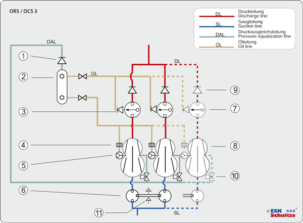
1 Pressure valve RV2-10B-1.5
2 Oil reservoir OSA
3 Check valve RV-10B-0.1
4 Strainer F-10B / F-10L / FF-10B
5 Oil level regulator OR .. / ERM6..
6 Suction line accumulator FA.. / FA..W
7 Oil separator OS / BOS2
8 Compressor, two stage
9 Check valve RV
10 Solenoid valve
11 Liquid line
Flow Diagram OCS 4 with low pressure oil reservoir
Compressors, single stage with different suction pressures
For the oil management of multi compressor system, which have common discharge line, but separate suction lines with different suctions pressures, the following pints should be considered:
1. The pressure equalization line is to be connected with the suction line which has the highest working pressure.
2. The compressors working with lower suction pressure are to be equipped with adjustable oil level regulators type ORE2.. (up to a maximum pressure difference between suction and oil reservoir pressure of 6.5 bar) or with electronic oil level regulators type ERM5.. .
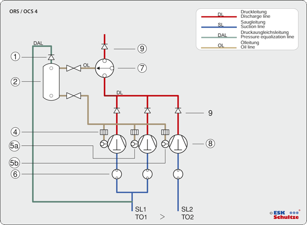
1 Pressure valve RV2-10B/1.5
2 Oil reservoir OSA
4 Strainer F-10B / F-10L / FF-10B
5a Oil level regulator OR .. / ERM6..
5b Oil level regulator ORE 2.., ERM6..
6 Suction line accumulator FA
7 Oil separator OS / BOS2
8 Compressor
9 Check valve RV
Flow diagram OCS 5 with high pressure oil reservoir
The system is equipped with a combination of an oil separator reservoir. No float valve is installed into oil separator reservoir. The oil has condensing pressure and will directly feed to the electronic oil level regulators. Electronic oil level regulators of type ERM5 are approved for high pressure applications and described in detail in our catalogue on page 42. The technical advises on page 10 should be considered. A long-term approval of systems with high pressure oil reservoir is mandatory. Mechanical oil level regulators are not suitable for this application.
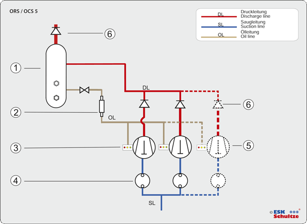
1 Oil separator reservoir OSR / BOS2-R
2 Strainer FF-10B / F-10B
3 Oil level regulator ERM6..
4 Suction line accumulator FA..
5 Compressor
6 Check valve
Flow Diagram OCS 7 for CO2 booster systems
The oil management for a typical CO2 booster system is shown in the diagram. ESK is offering suitable components for the different pressure levels. On the high pressure site components for up to 130 bar can be equipped. The selection of the other components depends on the concept of the refrigeration unit. ESK provides components for the pressure levels 45 / 60 / 100 bar.
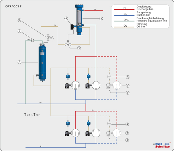
1 Compressor MT
2 Compressor LT
3 Oil separator BOS3-CDH
4 Level control OSC-1
5 Solenoid valve MV-11W-1-CDH-P
6 Oil reservoir OSA-CDM / OSA-CD
7 Pressure valve RV2-4,5-CDM / RV2-10B-1.5-2W
8 Strainer F-CDM / F..
9 Oil level regulator ERM6
10 Safety valve
|
|